Book a Session
We are located at:
440 Gateway Plaza Suite F
DIXON, 95620
Like Us on Facebook!
Find out about special offers and promotions offered only for our Facebook fans.

Fixing A Kodak Carousel That Does Not Advance

Download a PDF version of these instructions here now.
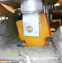
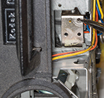
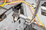
These instructions are designed to help you fix a 1966-1981 vintage Kodak Carousel Slide Projector which does not advance. If your projector is of this series, it will have a hinged handle on the front next to the lens, like in the photo above and will be black or grey, or it will have imitation wood grain side panels. If your projector has a model number that is greater than 1000, or is a 5XX series or is an Ektagraphic III, it is NOT covered by these instructions. The model 600 and 600H were part of this same series, but they do not have this issue.
The "does not advance" problem is caused by a plastic part called the "Cycle Solenoid Link" that gets brittle and breaks due to age.

You can confirm that your projector has this issue by pressing the forward and/or reverse buttons while there is NO tray on the projector and by observing the Indexer Lever (tray advance arm). You may very well hear a click when depressing the buttons, but the Indexer Lever will not move. If your indexer lever moves, then the issue isn't the cycle solenoid link, but possibly a defective slide tray. Kodak's 140 slide trays have problems of their own and are not recommended. Use the 80 trays.
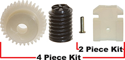
If you have determined that your projector is covered by these instructions, we need to next determine if your projector has remote or auto-focus as a feature. This is to determine if you need to buy the four piece repair kit with the focus gears, or just the two piece kit. If your projector has focus gears, they will also need to be replaced, as they are sure to be brittle.
The Carousel 650/650H, 700 & Ektagraphic E/E-2 require the two piece kit. All other models have either remote and/or auto-focus and require the four piece kit as shown above.
Tools Needed
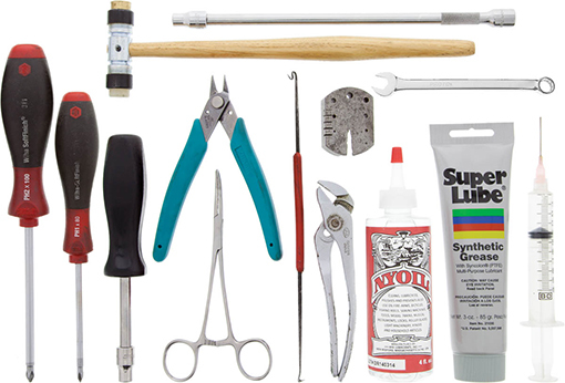
- #2 Phillips Screwdriver
- #1 Phillips Screwdriver
- ¼" Nut Driver
- ¼" Combination Wrench
- Hemostats
- Small Side Cutters
- Spring Hook
- Pliers
- Small Metal Block
- Small Hammer
- ¼" Socket on a Long Extension
For regular maintenance while you are in there, you will need the following:
- Super Lube Grease
- Needle Applicator for the Grease
- Light Oil
When it comes to the recommended lubricants, Kodak recommended "Super Lube" for the grease and they were not particular on the light oil. Before going out and buying more tools, read through these instructions and see how they are used and you may find something else in your tool box that will accomplish the same task. For example, I rarely use the combination wrench but instead use an extra-long reach nut driver in some areas and a flexible shaft nut driver in other areas.
Disassembly
- Unplug the projector, then remove the projection lens and any accessories stored in the accessories compartment. If your projector is of the "Custom" series (wood grain panels), see the "Custom Series Disassembly" further on for your initial disassembly.
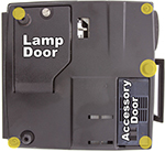
- Remove the bottom cover. You will need to remove four Phillips screws. Two of these are readily visible. You will find one more under the lamp door and the last under the accessory door. Note three of the screws will be the same and the one that was exposed and in the back corner is longer. You will also have to remove the front leveling foot. This foot is either a push on type or held on by a visible screw. If your projector is the style where the lamp door stays attached to your projector after the bottom cover has been removed, you will need to close and latch it, ensuring it is firmly closed. Failure to close this door may lead to your condenser lenses dropping out and breaking.
- Remove the accessory compartment wall. This is held on by three ¼" headed screws. If you have a circuit board attached to this wall, lift the whole wall up and out of the way after the three screws have been removed.

- Remove the front elevating foot bracket, which is held on by two ¼" headed screws.
- Remove the focus motor bracket if your projector has one. This is held in by three ¼" headed shouldered screws. This is where the extra-long reach ¼" nut driver comes in handy.
- Finish breaking off the two focus gears, as this will help you gain better access to the solenoid mounting plate, not to mention that you need to replace them later in this process.
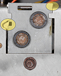
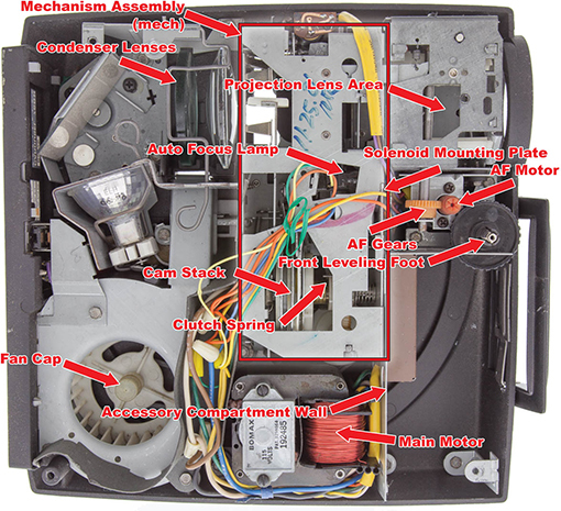
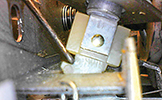
- Remove the solenoid mounting plate. Before doing so, note the position of the notch on the left and how far the plate sticks up above the mech housing. This solenoid mounting plate slides up and down as an adjustment. Putting it back together in the same alignment as when you took it apart will help alleviate the need to readjust it. Remove the two screws that go through the rubber grommets first, as these are the ones that actually go into the solenoid. Last but not least, remove the bottom adjusting screw. Completely remove the solenoid mounting plate from the mech.
- Remove the solenoid plunger from the solenoid. I like to turn the projector on its side (forward and release buttons facing the table) and I use the spring hook and get the plunger to fall downwards towards the area where the lenses are. I then rotate the projector 90 degrees (counter clockwise) so that the main lens would be facing the table and I shake the plunger the rest of the way out of the projector. Before doing this, ensure that the bracket holding your condenser lens in is secure. Be careful to not hit or move the small auto focus lamp if you have one.
- Remove the plastic link and rivet from the plunger. I use a pair of heavy duty small side cutters to do this. Be careful to not break the link mount off of the plunger.
Custom Series Disassembly
- Remove the bottom cover by unscrewing the coin-slot screw, then pull the bottom cover off of the hinge. The cover is just snapped onto the hinge.

- Remove the side cover that is closest to the lens. This is held on by three ¼" headed screws. One is visible by the projection lens area and the other two are hidden under the paper baffle behind the mirror. Be careful to not rip the paper.
- Remove the screw that is closest to the front of the projector which is holding the opposite side plate.
- Remove the front cover, which is held on by two screws going down into the top housing and one smaller screw that is now exposed, due to the side plate being removed.
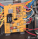
- Be careful with the auto-focus control board, as the clips that hold the wire to the board can break. If this happens, you will need to solder the wire to the board.
- Continue on with step 5 in the previous disassembly section.
Repair & Reassembly
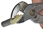
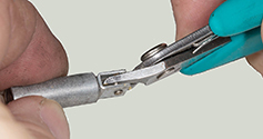
- Attach the Cycle Solenoid Link to the solenoid plunger. Using a pair of pliers, squeeze the rivet to secure the link to the plunger. If you have a rivet punch, that is an even better way to accomplish this.
- Insert the plunger into the solenoid. Using your spring hook, hold the solenoid so that the plunger hole is facing out through the access. With your hemostats, grab the plunger by the link and insert it into the solenoid. While still holding onto the link, push the plunger and solenoid back into the mech assembly. This may be a little tight but it will work. Be sure to NOT bump up against the auto-focus lamp. The auto-focus lamp can be moved around in its socket and this is an adjustment that you don't want to do if you don't have to.
- Attach the link to the internal arm by inserting the back side of the fork in first, then pressing down on the front side with either your hemostat or spring hook.
- Re-attach the solenoid mounting plate in the same position that it was when you took it off. Attach the plate to the mech with the adjustment screw first. Using your spring hook, align the solenoid so that you can mount it to the plate with the 2 remaining collared screws.
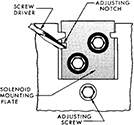
- Cycle Solenoid Adjustment: Solenoid should operate without chatter. To adjust for minimum noise, loosen the adjustment screw slightly, insert a screwdriver into the notch and raise or lower the solenoid mount as necessary. Tighten the screw. If the solenoid stroke is too short, reverse cycle will not work. There is a good chance you will not need to do this.
- Make sure all remnants of the old gears are removed from the focus motor and shaft for the gear next to the focus motor.

- Install the 167348 gear (gear next to focus motor). Turn the projector onto its side again with the forward and reverse buttons facing toward the table. Again, make sure your condenser lenses are secure so that they don't fall out. VERY IMPORTANT: support the back side of the shaft with a metal block while pressing the gear on. Using your ¼" socket on a long extension, with your hammer, tap the gear onto the shaft. Yes this is a tight fit but it will work.
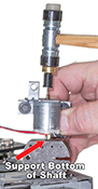
- Install the focus motor gear. Again VERY IMPORTANT: support the back end of the focus motor shaft while installing the gear. Lightly tapping the gear with your small hammer will get it on.
- Re-install the focus motor bracket.
- Re-install the front leveling foot and accessory compartment wall.
Service/Preventative Maintenance
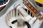
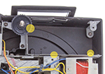
- The first step in servicing is to remove all the old dirt and junk that has accumulated inside your projector over the past 35+ years. If your projector has a big resistor over the top of the fan, this is used to provide the low setting for your lamp. If it is flaking like in this photo, just blow all the flakes out and let it be. If it were defective the only thing that wouldn't work is the low lamp setting. I actually blow out the projector with an air compressor as soon as I remove the bottom cover.
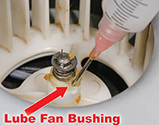
- Lubricate the fan bushing. Remove the fan cap and insert the tip of your grease applicator in-between one of the slits in the bushing. You know you have enough grease when it starts coming out the other two slits. There is one slit that will give you better access than the other two. Re-attach the fan bushing cover.
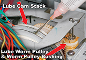
- Lubricate the Cam Stack. Using your grease applicator, apply grease to all slots on the cam stack and don't forget the outside one closest to the fan.
- Lubricate the Worm Pulley with grease.
- Lubricate the Worm Shaft Bushing (just like the fan).
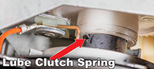
- Lubricate the Cam Stack Clutch Spring with light oil. Spraying WD-40 in here even works better. What you are actually trying to do is loosen up some old grease that gets gummed up in here.
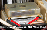
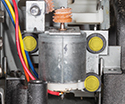
- Lubricate the Main Motor. There are 3 main styles of Main Motors. The first being the one with a metal cover that says "Bomax." These are not serviceable. The other two types have plastic covers on them. One of them is solid like pictured here and needs the cover removed to apply oil to the pad/sponge. Be careful to NOT break off the tabs. The last is the most common and it has a plastic cover that has an opening that allows direct access to apply the oil. You know you have applied enough oil when the pad/sponge is totally soaked (dark).
- Reinstall the bottom cover and front leveling foot.
- Test for proper operations.